For this
installment, I’m going to finish up on track installation and move on to
some wiring.
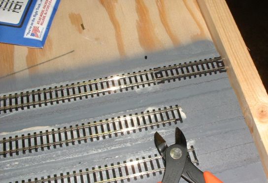
In photo number 1,
I’m cutting the track to length at the end of the modules to accommodate
the 5” Atlas Snap-Track pieces (Atlas item #2501) that are used to join
the modules. The simplest way to
accomplish this is to get the Atlas Snap-Track short section assortment (Atlas
item #2509) and use the ~2 ½ inch piece (the longest of the assortment)
to mark the track. This is done by
clamping a board to the end of the module and butting the Snap-Track piece
against the clamped-on board. You
can then mark the spot to cut your track.
Rail nippers, a Dremel tool or a razor saw will do the job. I did find that some trimming of the
track when actually joining the modules is still necessary, however.
1.
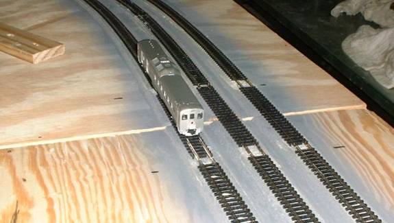
In photo number 2,
I’ve joined the modules together using 3 inch C clamps on the underside
and fitted the ‘joiner’ tracks. Here I’m test running a Kato RDC
to be sure everything works after hooking up a power pack with some alligator
clips. By golly, it works! Just wait ‘till I hose up
something later!
2.
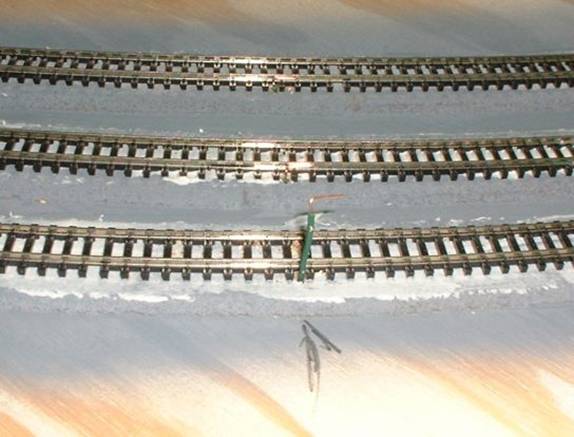
Next, I’m
installing the feeder wires before I paint the track brown. In this case I used 22 gauge solid-core
wire for the hook-ups, soldered to the outside of the rails on each
module. Each wire is stripped about
½ inch, bent to an L shape at the end and fed through a small hole
drilled between the ties on the outside edge. Flux is applied, and we solder away,
essentially in the same manner as I described when joining track sections. See photos 3 & 4.
3.

4.
Note that I used
green wire for the rails closest to the front of the module on each set of
tracks and black for the back rails.
I would have used red instead of the green, but had no red and lots of
green left over from previous projects.
You can use whatever you want.
I find using different colored wire helps to keep things straight.
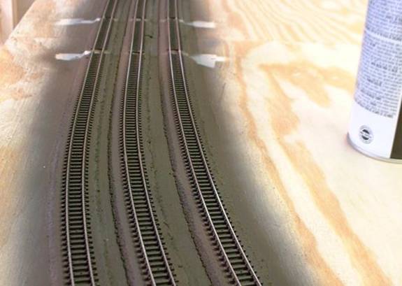
After all of the
feeders were installed, I next painted all of the track a flat brown. I used a flat brown camouflage spray
paint made by Krylon purchased at my local hardware store. This was the closest match I could find
to Polly-Scale Railroad Tie Brown, which I think is a good all-around color for
this, and using a spray can eliminates the need to fire up the air brush…
and its more economical. Just be
sure to do this outdoors or in a well ventilated area. See picture 5. Note that I put tape over the
joints of the joiner tracks, and also over the points of any turnouts (since I
use Peco turnouts which are power routing via the points, getting paint in
there can be problematic). Touchup
to these areas can be done later with a brush, if need be.
5.
Lesson learned
here: Painting the roadbed grey
first was probably not worth it, however, I did go back later and re-spay the
roadbed under the joiner sections grey, since these areas will not be getting
ballasted.
I painted small
sections at a time and before the paint dried I went over the tops of the rails
with a Bright-Boy with a rag wrapped around it to remove the bulk of the
paint. Later, I went over all the
modules with a Bright-Boy to be sure all of the rail tops were completely clean. Some magazine articles have suggested
coating the tops of the rails with a light application of oil prior to
painting… I have never tried this, so I can’t really comment on
whether that helps. The method I
used is relatively painless if you work methodically and in short sections
(say, 2 feet) at a time.
Ok, now onto the
wiring. The first thing I did was
make 3 mounting ‘plates’ for the female Cinch-Jones chassis-mount
connectors that go on the left side of each module. Cinch-Jones connectors are called for in
the N-Trak standards. Since they
are an old design, they can be difficult to find, but are readily available
from the ntrak.org website. The Cinch-Jones connectors are sold in
pairs (1 each of male and female connectors with the female connectors either
chassis mounted or not). I made
each mounting ‘plate’ from a 10 inch scrap piece of 1x4
lumber. The holes were drilled with
a ¾ inch wood boring bit.
The three holes grouped together are for the bus wires to the three
community tracks. The fourth hole
is for the AC accessory bus. See
photo 6.
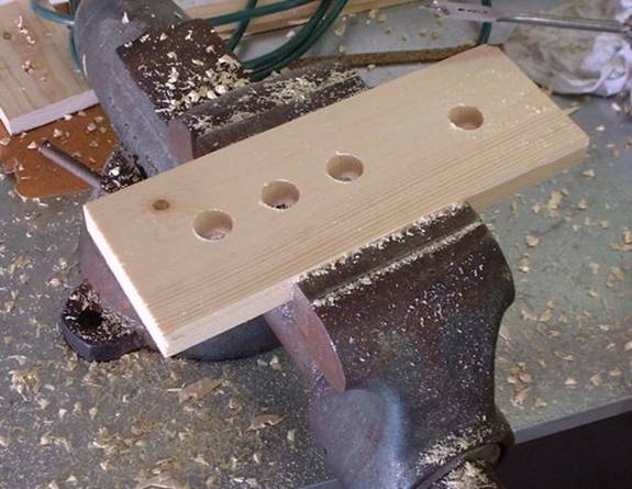
6.
In photo number 7,
I’m soldering the wires to the Cinch-Jones connectors. For the track buses, I used 18 gauge red
& black speaker wire (from Radio Shack), and for the AC line, 16 gauge
white speaker wire (also from Radio Shack). The N-Trak standards call for the wide
pin of the Cinch-Jones connectors to correspond to the rail on each track that
is closest to the front of the module.
For this, I used the red wire, the black for the rear track.
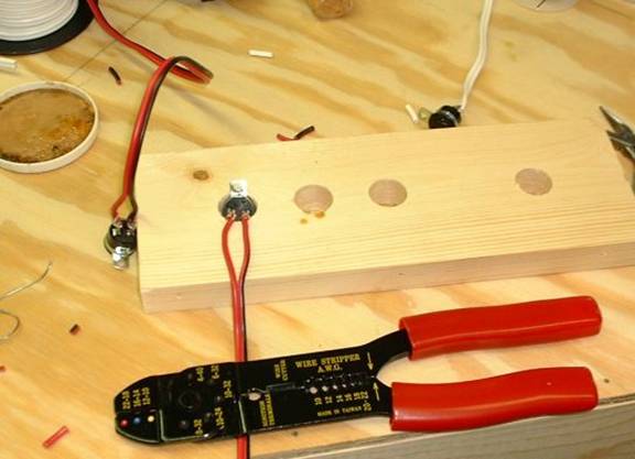
7.
After the wires
have been attached, the Cinch-Jones connectors are mounted in their holes with
brads or small screws and the mounting ‘plate’ is attached to the
underside of the module with glue and screws. See photo 8.
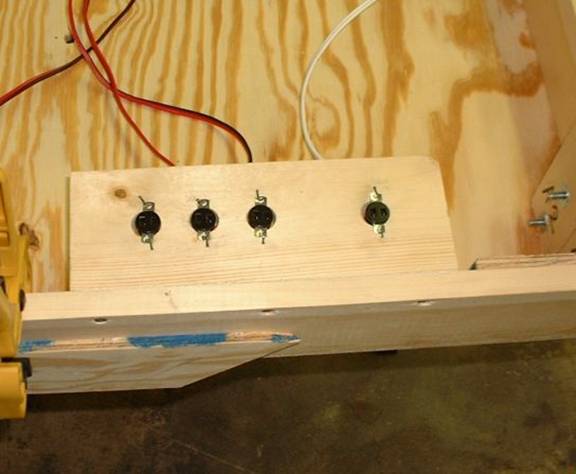
8.
Lesson
learned: My 15 watt, needle tip
soldering iron wasn’t quite up to the task of soldering the wires and
connectors together, so I used a soldering gun. I would NOT recommend you use a
soldering gun to solder track though, as they get so hot that plastic ties will
turn to puddles of goo almost instantly…
Now, onto the other
end. Essentially the same thing,
except the wires hang free. The
N-Trak standards call for 20 inches of ‘free’ wire to hang below
the module for joining to the next.
The male ends of the Cinch-Jones connectors are in 2 pieces, a sleeve
and the connector itself which you solder the wire too. Be sure to fit the sleeve over the wire
BEFORE you solder on the connector.
I didn’t do it this time, but I’ve made that mistake before
(remember, measure 10 times, cut once!.. Murphy is always hiding just around
the corner). I anchored the bus
wires to this end of the module with some cable staples. See picture 9.
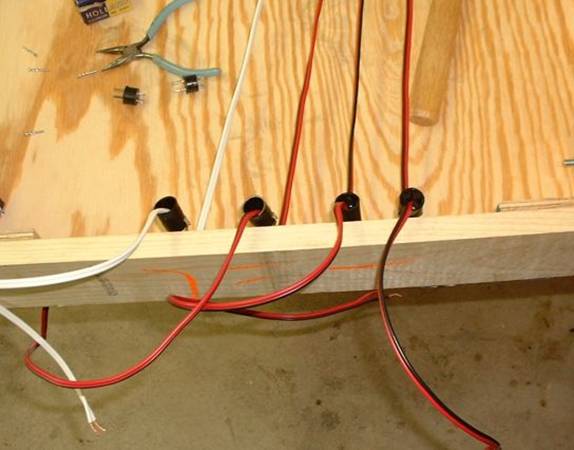
9.
After all the
soldering is finished, I connected the bus wires to the feeder wires with some
‘suitcase’ connectors.
The N-Trak manuals suggest using terminal strips, or you could solder or
use other solderless connectors… your choice. See picture 10.
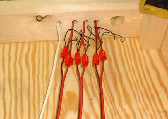
10.
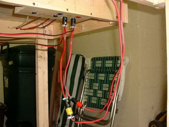
Finally, in picture
11, the cables and connectors on both ends are color-coded per the N-Trak
standards. Starting with the track
closest to the front, they are labeled red, yellow and blue. I used colored electrical tape for
this. The AC line is white, and
since I used white cable, I didn’t do any additional labeling. Note, on the AC line, the wide pin will
be connected to the + terminal on your power supply.
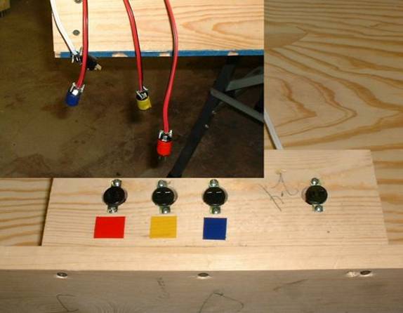
11.
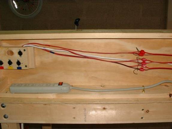
In finishing up
the wiring, I added the outlet strips to each of the modules as called for in
the N-Trak specifications for providing ‘house’ current along the
length of the assembled layout. Photo 12 shows the underside of a
bridge module with the outlet strip attached. Per the specifications, the outlet strip
must be easy to remove in order to meet local fire codes when setting up a
display, so the strip is not permanently screwed in place, but rather slipped
over screw heads in the side of the module. The cord is then anchored with
‘clip’ type cup hooks (see N-Trak manual) as can be seen in the
right of the photo.
2006 Update
Note: Daisy-chained outlet strips to provide 120 VAC power around
the layout is no longer an N-Trak Recommended Practice due to changes in many
local fire codes. Please see The Ntrak Module “How-to” Book and/or
ntrak.org for current layout wiring
specifications.
So, do not do this, or if an existing
module, remove the power strip:
12.
Lastly, I
constructed throttle connection wires with some additional Cinch-Jones
connectors. These are described in
the N-Trak manual also. Note that
on the end that connects to the throttle, I spliced on both spades and female
push on connectors. The female
connectors are because I am probably one of the few people on earth that still
has a Troller throttle. See photo
13.
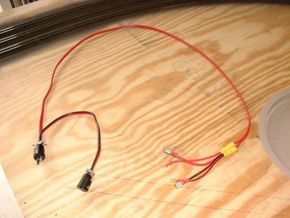
13.
Photos 14 & 15
show how the throttle connectors attach to the modules (the modules here are
not clamped together) and to the throttle which is on (sorta) portable control
panel that has casters on the bottom.
14.
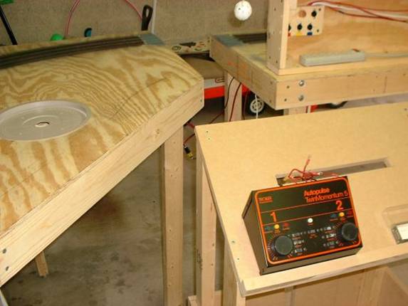
15.
2006 Update:
Chassis mount
Chinch-Jones connectors as used above for the ‘female’ connections
are no longer available from the ntrak.org
website. They may be available from
other sources, however.
Additionally, the N-Trak
standards, revised in 2006, now have a recommended Practice of using Anderson
Powerpole connectors for newly constructed or refurbished modules. While Cinch-Jones connectors are still
the ‘standard’, Powerpoles are much less expensive. There also has been an update
recommending the use of 12 gauge wire for the main buses.
Please see The Ntrak Module “How-to” Book and/or
ntrak.org for complete information.