These pages originally developed in July, 2004 and Updated as noted.
These pages describe, the construction of (2) four-foot corner modules, and (1) 2x4 straight module. These modules are being constructed using the ‘instructions’ in The NTrak Module “How-to” Book”. I would strongly suggest you obtain or borrow a copy of this, as the smaller NTrak Module Manual pamphlet is somewhat vague due to its brevity… but that could just be me. The big book is $12 $16 from ntrak.org, and well worth it. It is worthwhile to study the diagrams closely, especially if you are going to be building corner modules.
The modules I am
constructing here have frames constructed of 1x4 pine, and topped with 3/8 inch
BC grade plywood. The glue blocks are made from 2x2 studs.
Everything is held together with 2” deck screws and Elmer’s Carpenter’s Wood
Glue (I used the outdoor variety, not because I will be modeling an underwater
scene, but because of the wonderful humidity here in
So, on to photo
number one. Here we have cut all of the parts to make the frames for the
three modules. Mind you, this was only after making a big pile of
kindling, thus my recommendation that you get the big book, and read it….
Really. The bucket has the glue blocks in it.
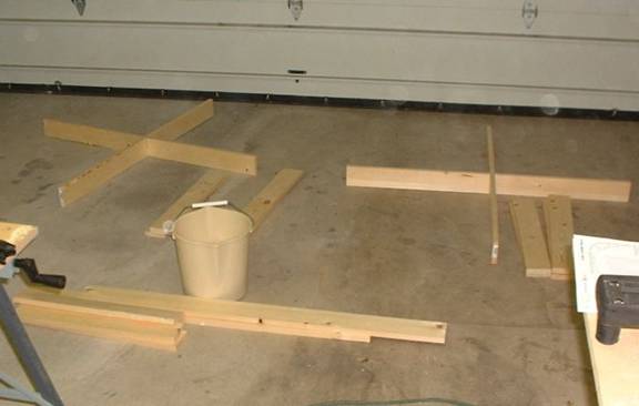
1.
Photo number two
shows starting to install some of the glue blocks. Since pine likes to
split, do drill pilot holes first. Lesson learned: don’t tighten any of
the screws all the way (leave them out about ¼ inch) until you attach the top
so that you can square the whole assembly up. Also, the NTrak manuals
mention countersinking your screw holes. I don’t think this is really
necessary with pine framing and decking screws. A variable speed
drill or driver for screwing is a must so as not to drive them in too far…. And
to think 20+ years ago I assembled benchwork with a screw driver. A Nobel
Prize should be awarded to the man who invented the screw driver bit.
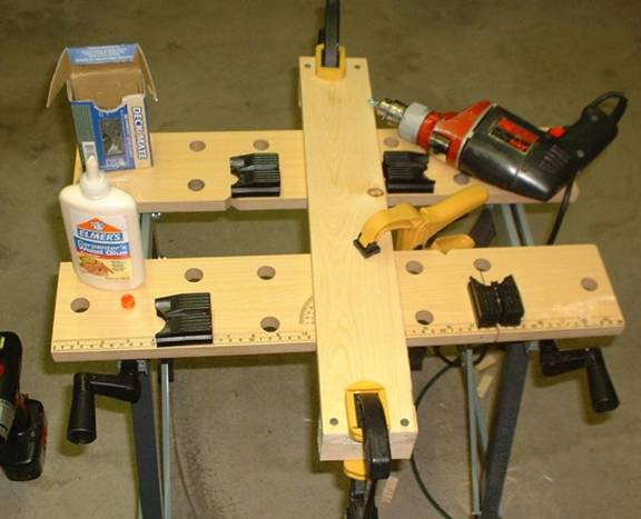
2.
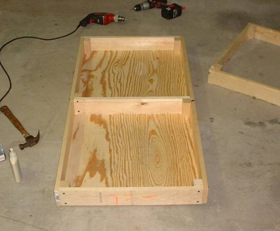
Continuing on, in
photo number three, I have test fit the parts to construct the two ~ 2 foot
‘boxes’ that comprise the corner modules. Note that I used the ‘notch’
method for joining the two boxes at the center (the X). I felt this was
easier and more flexible than using a butt joint at this location. Big
note here: the notch is not in the center of the cross pieces. The
NTrak manuals are vague on this point. If you are using 1x4’s, the cross
pieces are 47 ¼ inches. The edges of the notches are 22 ½ inches from one
end and 24 inches from the other. Knowing this ahead of time will reduce
you kindling pile in the end. (120.015 cm, 57.15 cm, and 60.96 cm
respectively. Boy I’d hate to see that ruler.)
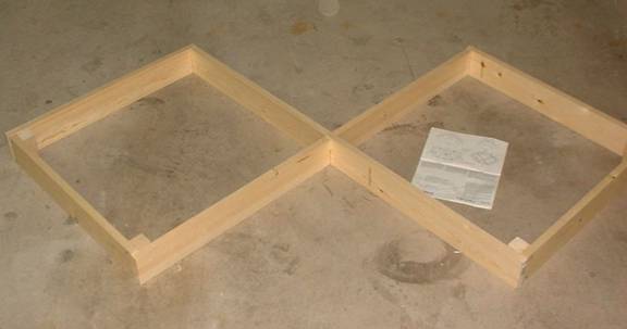
3.
At this point I
installed the rest of the glue blocks as shown in NTrak’s diagrams. Glue
blocks at the center are optional when using the notch method, but I added one
later for additional rigidity after I installed the top and the assembly was
square. I should note that my local Home Depot does not carry un-treated
pine 2x2’s, so I just trimmed down some 2x3 pieces, or 2x3’s would have been
fine. The legs will be made from 2x3’s.
In photo number
four, I’ve laid a bead of glue around the edge of the 2x4 module in order to
install the top. Again, leave the corner screws backed out a bit until
the top is on and the assembly is square.
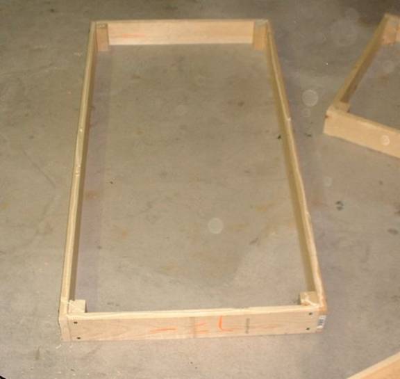
4.
Next the top is
installed. I used small 1 ½ inch finishing nails to secure the top,
making sure things were square as I went. It must have been a good day
because I managed to nail down the tops on all of these modules without
smashing any digits!.
In photo number
five, after the top was secured, I installed the center brace. Use of the
center brace precludes the use of folding leg schemes, but I decided to go with
simple bolt on legs for my first go at this.
5.
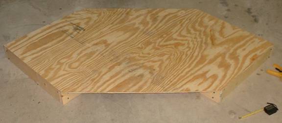
Moving back to the
corner modules now, in photo number six, I’ve secured the tops to them.
The tops are 4x4 pieces of plywood that have been trimmed (2 corners cut off)
with a circular saw. Note that I have not yet installed the center
braces. I felt that it would be easier to make these after the top was
installed and the assembly was square (it was).
6.
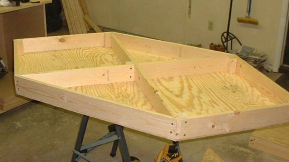
Photo number seven
shows a corner module with the ‘end’(for lack of a better term) pieces
installed. The NTrak manuals are extremely vague as far as the dimensions
of these pieces, stating something to the effect: ‘approx. 3’, cut to
fit’. Well, actually, these pieces are just a hair shy of 33 inches on
the one side and 34 inches on the other. I think I had to trim about 1/8
of an inch from each end to get them to fit well. Each end is a 45 degree
angle.
7.
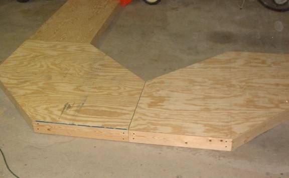
Photo number eight
shows the 3 frames assembled and test fit together.
8.